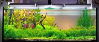
Hello, Muskovites! My wife and I became interested in the aquarium back in 2015. We immediately started making a herbalist - ADA PowerSand + ADA AquaSoil Amazonia soil, CO2 supply and a lot of light. I then made a homemade aquarium lid with built-in fluorescent lamps. For several years, the herbalist pleased us with his amazing appearance, but at some point, my wife got tired of the process of caring for him and the aquarium from the herbalist was converted into a purely fish tank. The only light left was one T8 18W lamp. Over time, problems began: mold began to appear from inside the lid of the aquarium, although this had not happened before, apparently the abundance of light helped. In general, it was decided to make the aquarium open, hence the idea of this lamp was born. Read on to find out what came of it. Our aquarium once looked like this: Two T5 24W lamps (Sylvania Grolux and Aquastar) and one T8 18W (Sylvania Daylightstar) were installed in the lid of the aquarium. In terms of illumination, it turned out to be somewhere around 1 watt per liter (for some reason, the brightness of fluorescent lamps was counted in watts, not lumens). And this illumination was quite enough for our herbalist. The cabinet for the aquarium, by the way, is also homemade:
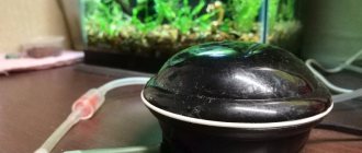
And this is how the lamps shone:
Now the aquarium with the new lamp looks like this:
The size and power of the new lamp are designed for a herbal aquarium 60cm long with a useful volume of about 65l (total 85l). It should be noted that for a herbalist like Aman’s, this is the very minimum in terms of lighting intensity for a given volume. It is believed that an overclocked herbalist (with CO2 supply) needs about 40-50 lumens per liter of water (depending on the density of the plants). So my 65 liters require a light level of 2600 to 3200 lumens. The selected LEDs each provide about 120 lumens for white and about 20 lumens for color. Which in total should give a luminous flux of 2320 lumens... Well, in general, almost...)) White LEDs for an aquarium are recommended to be used with a color temperature of 6500K. However, I didn’t find any such ones and used the usual 4500K.
The use of LEDs in the lamp opens up additional possibilities, such as brightness adjustment. Naturally, I decided to take advantage of this and I also wanted to make an imitation of sunset and dawn. To do this, I needed LED drivers (homemade) with the ability to supply a PWM signal, as well as a microcontroller, I used an ESP8266 (D1 Mini board) and the Tasmota project firmware.
There are quite a few options for making such lamps; I personally made them from materials and components that I had in stock at home or were sold at the nearest hardware store. Therefore, my particular copy of the lamp is slightly different from the drawings and models given below in the article... Some use radiators from computer processors, others install active cooling... My version without all this, but as practice has shown, the heat capacity of the used aluminum the profile is quite sufficient to effectively remove and dissipate heat from 26 1 W LEDs. After several hours of operation, the temperature of the radiator can be tolerated by the hand without straining (it would be necessary to measure it).
The lamp is made of aluminum profile, 18 cool white LEDs (1W), 4 red 650nm and 4 blue 450nm LEDs. Colored LEDs are necessary to compensate for the unevenness of the spectrum of white LEDs (although I did not make any special calculations for this).
Characteristics of white LEDs
Assembly
Briefly about the assembly. 3D model in sketchup. The base of the lamp is made of sections of aluminum profile 15mm x 30mm. Aluminum parts are folded in pairs on edge, securely fixed and drilled with a 2.5 mm drill. Moreover, both walls of the upper profile are drilled, and only the adjacent wall of the lower one. In the upper profile, the holes located on the upper edge are drilled to 7mm. Next, the parts need to be separated and an M3 thread must be cut in the lower profile, and a hole must be drilled in the lower wall of the upper profile with a 3mm drill (so that the M3 screw can pass through freely). Thus, a pair of profiles is fastened with M3 screws at 5 points. After connecting the first pair of profiles, we disassemble everything, having previously marked which profile connects with which, remove the top profile, put the next profile down and repeat everything, but with some offset. I tried to depict this in the illustration:
After preparing all the parts, the contacting surfaces must be coated with a thin layer of thermal paste (I used KPT8).
Assemble the parts of the lamp base by tightening them with screws using thread locker. If in your case the LEDs get on the joints of the profiles, then for normal thermal contact between the profile and the LED heat sink you need to carefully sand the entire surface. In the drawings presented here there is no such problem, however, because I assembled my lamp from materials that were at hand, then I was faced with the need for grinding. We select the side to which we plan to attach the LEDs and carefully grind it until the finger no longer feels the transition between adjacent profiles (I sanded first with a grinder with Velcro sandpaper, and then with a vibrating surface grinder Fiolent MPSh 4-28 with 400-grit sandpaper). Next, we attach aluminum corners on both sides. I used 25x15, but it's better to get a larger size. Fastening with M4 screws, into pre-drilled holes, 3.5 mm in diameter with cut M4 threads.
Next, we attach an W-shaped profile on top - it will serve as a radiator. We coat each part with thermal paste and fasten it with M3 or M2.5 screws (M3 heads may not fit between the ribs).
The vertical posts are made of the same profile as the base of the lamp (15x30mm). For installation on the edge of the glass of the aquarium, parts from a U-shaped profile are fixed at the bottom of the racks at the corners.
The U-shaped parts have inserts made of felt and some kind of slippery plastic, which make it easier to move the lamp along the edge of the aquarium glass.
The housing assembly is complete, all that remains is to attach the LEDs. In any drawing program or vector graphics editor, we make a layout of the LEDs and print it on a scale of 1:1 on 2 A4 sheets, followed by gluing it into one template. We glue the model with a glue stick to the base of the lamp and mark the holes for fastening the LEDs. Layout example. Then we drill holes with a 2.5mm drill, cut an M3 thread and use thermal paste to install stars (Star-type radiators) of LEDs on the base. I would especially like to draw your attention to the fact that under the heads of the screws, in order to avoid short circuits, it is necessary to place insulating washers made of fiberglass (I bought them at Chip and Dip)
The LED drivers I used have the greatest efficiency when powered by 24V and connected in series with 6 one-watt LEDs, the circuit will be below. We connect all the LEDs according to the diagram (for installation I used 0.35 sq. mm MGTF wire) and then protect the contacts and all elements of the lamp facing the water with varnish (well, except for the LED lenses, of course). In the end it should look something like this:
Calculation of the number of diodes per driver.
Based on the characteristics of the drivers that I chose, they produce an output voltage of 52 Volts with an input of 56, which means that with a voltage from my power supply of 48 volts, the output will be 44, with a voltage drop across the diode of 3.2 (this figure must be looked at in the characteristics of the diode) we get 44/3.2 - 13 pcs. I decided not to install them end-to-end, but to combine 10 pieces of what I bought and combine - 9 pieces of drivers (I bought 6 pieces of LDD-700H for RB, CW, B and 3 pieces of LDD-500H - DR, G, UV, I wanted for Ultra diodes violet take the LDD-350H, but it wasn’t there).
Electronics
Drivers for powering the LEDs are homemade based on the MBI6651 chip in the SOT23-6L package. The boards are made for SMD mounting; the back side of the fiberglass laminate remains completely smooth, which allows them to be mounted on the back side of the profile, which serves as a radiator for the drivers.
These microcircuits from the harness require 2 tantalum capacitors, an inductor, a Schottky diode and a current-setting resistor.
There is an input for supplying a PWM signal to control brightness (from 0 to 100%). When powered by 24V and connected to 6 LEDs, these drivers provide an efficiency of about 98%. In my case, 5 such microcircuits were used. 3 drivers power 18 white LEDs, and one each is used for red and blue LEDs. In principle, it was possible to hang 8 color LEDs on one driver, because they have a lower supply voltage and are limited to four MBI6651 chips for the entire lamp. Two 0.47 Ohm resistors connected in parallel (in total they give ~0.23 Ohm) provide a current of about 350 mA. I used inductance with leads, placing it above the driver chip. For an SMD choke, additional space on the board would be required.
Board in SprintLayout6 format On the driver board, you need to connect all the “In +” spots with jumpers and connect the positive output of the 24V power supply there. Connect the general and output of the PWM signal from the microcontroller, which is described below: To control the light, a D1-mini module based on the Wi-Fi microcontroller ESP8266 with firmware from the Tasmota project was used.
The board with minimal modifications and the case were used from one of my previous projects of a dimer for LED strips. To power the D1 Mini board, a MINI 360 DC-DC converter was used at the input of which 24V is supplied.
The luminaire can be controlled from any smart home system via MQTT or GET requests. There is a web interface for initial configuration and management. Tasmota can also be configured for autonomous operation (various timers and scripts triggered by them). Thus, I have configured full automatic autonomous operation of the lamp, dawn and sunset modes are implemented (configuration will be described in detail below).
Questions at the planning stage.
When I started planning a diode lamp for a marine aquarium, I had a number of questions:
- what lamp sizes to choose
- how to fix this lamp
- what number of diodes is needed, their frequency spectrum, quality
— what drivers are needed for diodes, their number, what power supply
— Do you need lenses for diodes?
— is active cooling of the lamp radiator necessary?
- where to get a radiator for a lamp, diodes, lenses, drivers, power supply, etc.
I also thought for a long time and thought a lot about what kind of light to make for the aquarium. After looking through many forum threads and reading many books, I settled on the following option: ice light with an Arduino control unit. Spare parts are cheap, installation is elementary, installation diagrams are in abundance, firmware is also available, and the programming language is not complicated. The project was based on information from the website aqualogo.ru, thanks to the author Alex_M.
What I actually wanted from my lamp:
- sunset Dawn
- economical in maintenance and acquisition
— cooling fan control
- control of the moon
— corresponds to the style of all marine systems
I bought almost all the parts from China, and since everything comes slowly from there, I made orders at the stage of gluing the aquarium together and earlier (3-4 months in advance). Ordered: diodes, lenses, hot melt glue, Arduino nano, RTC clock, 5 volt relay for 2 channels, circuit boards, terminal blocks, soldering iron, soldering fat, solder, tweezers, connectors and much more for soldering, power supplies. Drivers and a power supply for diodes were purchased and delivered from Ukraine with the help of a good friend of aquarists, Maxim AQUARIUS.
So, practical implementation.
I decided to make my aquarium open, so the lamp had to be either rested on the sides of the aquarium or suspended. But taking into account the approximate future weight of the lamp, I decided to hang it.
Firmware and configuration
Since I initially set the goal to be able to control it from a smart home system, I immediately wanted to use the MySensors project that I liked. But at some point, realizing that laziness and lack of experience in programming Arduino (to realize all my wishes) could delay the production of the lamp indefinitely, I decided to use something ready-made and configurable during the work process. Among similar projects, I am familiar with WiFi-iot and a little worse with Tasmota (of similar ones there is also ESP Easy and ESPHome...). The choice of Tasmota was determined by a number of factors, such as the PWM frequency, which can be raised up to 4 kHz; built-in wakeup function (dawn), there really is no sunset, I had to do it manually; free in the end, unlike WiFi-iot, for example... and the ability to write scripts through Rules, which were not yet familiar to me at that moment (I had to take the time to figure it out))))... Tasmota firmware can be downloaded in the form of source code (which I would like to tweak something there to suit myself) or in the form of an already compiled binary, which can be immediately flashed into the controller. Let's use the second option, download the binary of the current version of tasmota and flash it into the D1 Mini board. For the firmware I used the NodeMCUFlasher program, you can also use Tasmota PyFlasher
When first launched, an unconfigured Tasmota launches its (name-name) Wi-Fi access point. After connecting, go to the address 192.168.4.1 and in the web interface that opens, the first thing we do is configure the connection to our Wi-Fi router (Configuration=>Configure WiFi). Having set the necessary parameters, click Save, after which the device will reboot and connect to your router. Next, go to Configuration=>Configure Module and select Sonoff LED (here you can also configure the connection of additional devices, such as buttons, temperature sensors, etc.). Returning to the main menu we will see the light controls.
In the original, the Sonoff LED module can control an LED lamp with warm and cold LEDs, and the top slider just adjusts the balance between them.
We don't need it, so we immediately drive it all the way to the left. Using the lower slider we will manually control the illumination of our aquarium. The Toggle button switches the state of the lamp from off to on and vice versa. You can try it! After successful tests, let's move on to more fine-tuning: Open the console and enter the PWMFrequency command and in response we will see RSL: stat/tasmota/RESULT = {"PWMFrequency":800} this means that the PWM signal frequency will be 800Hz. Not bad, but it could be better, so we write in the console: PWMFrequency 3760 (I read somewhere that it is recommended to make the PWM frequency for lighting not a multiple of the network frequency, which is 50Hz) in response we get: RSL: stat/tasmota/RESULT = {“ PWMFrequency":3760} Let's also enable a smooth change in brightness and the speed of brightness change with the commands: Fade 1 Speed 5 It is also necessary to set the time (in seconds) for which the wakeup function will work (dawn); values from 1 to 3000 are available. For experiments, you can set 20 seconds and give the wakeup command from the console to see how it works (the lamp should be turned off). This function can be used by adding a brightness value in percentage. For example, the wakeup 50 command will make, for the specified time in the WakeupDuration parameter, a smooth change in brightness from the current value to 50%. This way you can bypass the restrictions on the length of dawn at 1 hour (3000 seconds). To do this, we simply divide the dawn into several stages, for example from 0 to 30% in the first hour, from 30 to 70% in the second and from 70% to 100% in the third hour. It should be noted that the Fade and Speed commands entered above do not affect the wakeup function in any way, and changes in brightness in the dawn scenario occur a little stepwise (although if you don’t look closely, it’s not noticeable). But they will help us smooth out the sunset process, which we will configure using a sequence of Dimmer commands (indicating the value) collected in a script using the Rule tool. The Dimmer command can be tested by entering from the console: Dimmer 30, Dimmer 70, etc. There are many teams, you can find them all here. Any command can be executed according to a schedule, but first we need to provide our control module with access to NTP servers on the Internet or local network. By default, everything should work fine via the Internet (unless, of course, you specifically blocked anything on the router) and all we have to do is set up the time zone. To do this, enter the command from the console: timezone 3 (substitute your number for 3). You can check the correctness of the time using the time command; if the answer is correct, then the preliminary configuration of the module can be considered complete, you can proceed to writing scripts and setting timers. But if for some reason you cannot provide the controller with access to the Internet, there is only one way - to connect a real-time clock module, but this is beyond the scope of this article. Let's take a break from Tasmota and draw up an action plan in clear language, so: Daylight hours are divided into 4 parts: • dawn from 9:00 to 12:00 • zenith from 12:00 to 14:00 • 90% illumination from 14:00 to 16:00 :00 • sunset from 16:00 to 20:00
Dawn
divided into 3 stages, and after 14:00 the illumination is reduced to 90%. Stages are activated by global timers (Configuration=>Configure Timer):
In the Action field we set the value Rule, now this rule needs to be written.
In total, you can set 3 rules, each of which can contain a certain number of commands, limited to 511 characters. If the number of characters in the first rule is exhausted, then you need to start the second. You can familiarize yourself with the syntax here To enter rules, you will again need the console, open it and write everything in one line: Rule1 on Clock#Timer=1 do wakeup 50 endon on Clock#Timer=2 do wakeup 75 endon on Clock#Timer=3 do wakeup 100 endon on Clock#Timer=4 do dimmer 90 endon Activate the rule: rule1 1 In this rule we have written scripts launched by global timers 1...4.
Sunset
consists of 3 stages (since one rule consists of no more than 511 characters). Starts at 16:00 according to global timer No. 5 (Rule2). Continues at 19:00 according to global timer No. 6 (Rule3) and switches off at 20:00 according to global timer No. 6.
Since there is no “sunset” function in Tasmota, everything is implemented using the dimmer function, and pauses using the RuleTimer (there are 8 pieces). The procedure is described in Rule2 and Rule3 (the rule can only accommodate 511 characters).
For readability, I write everything on a new line, although you can try and copy-paste everything at once
Rule2 on Clock#Timer=5 do backlog Dimmer 80; RuleTimer1 1200 endon on Rules#Timer=1 do backlog Dimmer 70; RuleTimer2 1200 endon on Rules#Timer=2 do backlog Dimmer 60; RuleTimer3 1200 endon on Rules#Timer=3 do backlog Dimmer 50; RuleTimer4 1200 endon on Rules#Timer=4 do backlog Dimmer 45; RuleTimer5 1200 endon on Rules#Timer=5 do backlog Dimmer 40; RuleTimer6 1200 endon on Rules#Timer=6 do backlog Dimmer 35; RuleTimer7 1200 endon on Rules#Timer=7 do Dimmer 30 endon Activate: Rule2 1 Rule3 on Clock#Timer=6 do backlog Dimmer 20; RuleTimer8 1800 endon on Rules#Timer=8 do Dimmer 10 endon Activate: Rule3 1 General summary: • 9:00 – the beginning of dawn. Within an hour, the brightness increases to 50% (Timer No. 1) • 10:00 – continued. Within an hour, the brightness increases to 75% (Timer No. 2) • 11:00 – continued. Within an hour, the brightness increases to 100% (Timer No. 3) • 14:00 – decrease in illumination to 90% (Timer No. 4) • 16:00 – sunset begins. Reducing illumination to 80% (Timer No. 5). -16:20 Reduce illumination to 70% (Rule2) -16:40 Reduce illumination to 60% (Rule2) -17:00 Reduce illumination to 50% (Rule2) -17:20 Reduce illumination to 45% (Rule2) -17 :40 Reducing illumination to 40% (Rule2) -18:00 Reducing illumination to 35% (Rule2) -18:20 Reducing illumination to 30% (Rule2) • 19:00 – continuation of sunset. Reducing illumination to 20% (Timer No. 6). -18:20 Reduce illumination to 10% (Rule3) • 20:00 – turn off the lights (Timer No. 10) • 19:30 – 10% • 20:00 – Turn off (Global Timer No. 10) On the graph it will look like- then like this:
That's probably all, maybe I forgot to tell you about something, ask in the comments... The article turned out to be huge, I hope you like it and will be useful to someone... PS Because... Questions arise in the comments: why do fish need so much light? I’ll answer right here: Yes, of course you are right and fish don’t need that much light, but my wife and I dream of returning to a herbal aquarium. Everything is done with this in mind.
Mounting the lamp.
[Show slideshow]
After deciding on the dimensions of the lamp, it was necessary to decide how to mount it. I really didn’t want to go into the ceiling, and I didn’t want to go into the wall either. I decided that the entire system would be independent of the walls. Those. if desired, he took it and moved it, or suddenly moved. It became clear that the lamp mount would be fixed to the MK. The shape is clearly “L” shaped. I chose a height of 2 meters from the bulldozer and a profile of 40*20*2mm. I calculated the sizes of the parts, went to the “metal”, and cut them out. Since I want to run the wires inside the profile, I made additional cuts in the pipe before welding. Cooked it. Having secured it to the MK level, I drilled holes for the fastening bolts. This stand will be visible, which means its appearance should be excellent. I cleaned the entire structure of bumps and unevenness, painted it with anti-rust and only then two layers of black paint.
When the entire system was installed on the stand, it turned out that if you hang the radiator, its center will be shifted 7 cm to the rear relative to the center of the aquarium. I calculated the dimensions of the frame for the center of the cabinet, not the aquarium. Since I didn’t want to redo the frame itself, I decided to simply move the front suspension cables closer to the center of the radiator, due to which it should have extended by 6 cm. But after testing with the radiator, it became clear that I would have to extend the frame by 7 cm. They cut it off , welded, cleaned, painted. We welded it a little with rotation, we had to bend it to maintain the level.
Next I ran all the cables inside the frame. A total of 10 cables from the bottom 9 PVVSh 0.5x2 for diodes, 1 PVS 0.75x2 for the moon and cooling fans. I marked the ends of the cables with colored electrical tape so as not to get confused.
Why is the sun red
The sunset and sunrise of the red Sun has attracted the attention of mankind since ancient times, and therefore people, using all the methods available to them, tried to explain why the solar disk, being yellow, acquires a reddish tint on the horizon line. The first attempt to explain this phenomenon was legends, followed by folk signs: people were sure that the sunset and rise of the red Sun did not bode well.
For example, they were convinced that if the sky remained red for a long time after sunrise, the day would be unbearably hot. Another sign said that if before sunrise the sky in the east is red, and after sunrise this color immediately disappears, it will rain. The rising of the red Sun also promised bad weather if, after its appearance in the sky, it immediately acquired a light yellow color.
The rising of the red Sun in such an interpretation could hardly satisfy the inquisitive human mind for long. Therefore, after the discovery of various physical laws, including Rayleigh’s law, it was found that the red color of the Sun is explained by the fact that it, as having the longest wave, scatters much less in the dense atmosphere of the Earth than other colors.
Therefore, when the Sun is at the horizon, its rays slide along the earth's surface, where the air has not only the highest density, but also extremely high humidity at this time, which delays and absorbs the rays. As a result, only rays of red and orange colors are able to break through the dense and humid atmosphere in the first minutes of sunrise.
Why buy LEDs with the highest luminous efficiency and then limit their brightness?
The point is to avoid shadow areas and evenly illuminate the bottom, it is necessary to place LEDs every 8-15cm. But with such placement, we cannot know in advance whether there will be enough light or, on the contrary, there will be an excess. So, if we suddenly have an excess of any spectrum, using the controller we can reduce the brightness of this channel. In addition, if the LEDs do not shine at full power, then their service life increases, and when their brightness decreases, we always have a reserve that we can turn up in the controller.
External characteristics of a wondrous natural phenomenon
Since the sunrise and sunset can be spoken of as two identical phenomena that differ from each other in the saturation of colors, the description of the sun setting over the horizon can also be applied to the time before sunrise and its appearance, only in the reverse order.
The lower the solar disk descends to the western horizon, the less bright it becomes and first turns yellow, then orange and finally red. The sky also changes its color: at first it is golden, then orange, and at the edge - red.
When the solar disk comes close to the horizon, it acquires a dark red color, and on both sides of it you can see a bright streak of dawn, the colors of which from top to bottom go from bluish-green to bright orange tones. At the same time, a colorless glow forms above the dawn.
Simultaneously with this phenomenon, on the opposite side of the sky, a stripe of an ash-bluish hue (the shadow of the Earth) appears, above which you can see a segment of orange-pink color, the Belt of Venus - it appears above the horizon at an altitude of 10 to 20° and in a clear sky visible anywhere on our planet.
The further the Sun goes beyond the horizon, the more purple the sky becomes, and when it drops four to five degrees below the horizon, the shade acquires the most saturated tones. After this, the sky gradually becomes fiery red (Buddha’s rays), and from the place where the sun’s disk set, stripes of light rays stretch upward, gradually fading, after the disappearance of which a fading strip of dark red color can be seen near the horizon.
After the shadow of the Earth gradually fills the sky, the Belt of Venus dissipates, the silhouette of the Moon appears in the sky, then the stars - and night falls (twilight ends when the solar disk goes six degrees below the horizon). The more time passes after the Sun leaves the horizon, the colder it becomes, and by the morning, before sunrise, the lowest temperature is observed. But everything changes when, a few hours later, the red Sun begins to rise: the solar disk appears in the east, the night goes away, and the earth’s surface begins to warm up.
Installing lenses for 3 W diodes.
Due to paint getting into the grooves, the lenses were difficult to insert. It was also difficult because I did it in the air on a hanging lamp, but it’s easier to insert the lens on the table and then glue it to the star. Conclusion, order the color of lenses that you need and you will save yourself from unnecessary suffering.
But this is not the end. When I connected the cabinet with electricity. I turned on the lighting again and the chain of pianos did not work. Armed with a tester, I found out that this time the reason was in the driver. But the next day the chain worked. I don’t understand what happened, but the main thing is that everything works. After a day of testing, everything worked without failures or incidents. The light is very bright, and it is only 70 percent of the power. From the street it looks like there is a UFO in the house